No Glass with all the Class
No Glass with all the Class
Click on the following product names and get exclusive access to our product specifications.
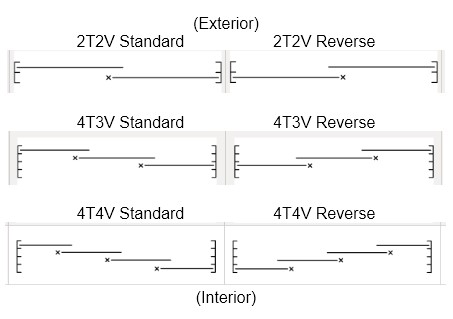
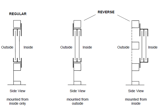
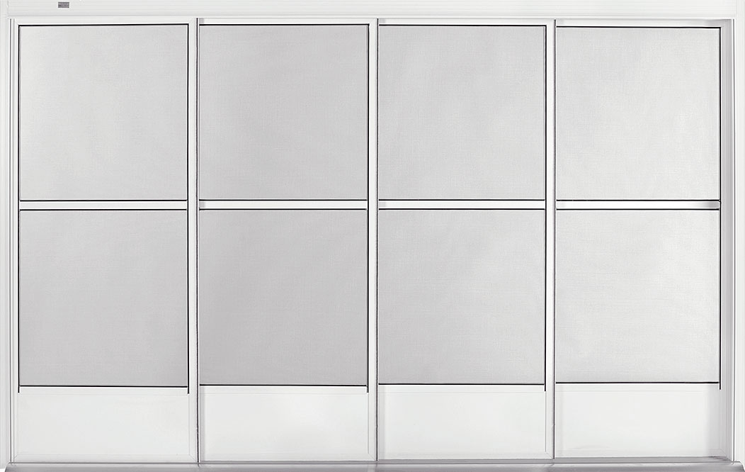
Note: All Eze-Breeze products are viewed inside looking out.
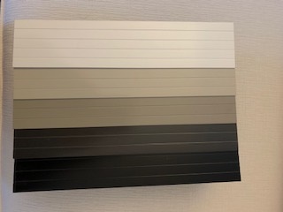
White
Bronze
Sandstone
Black
Pebble Khaki

Clear

Bronze

Smoke Grey

Muskoka Blue

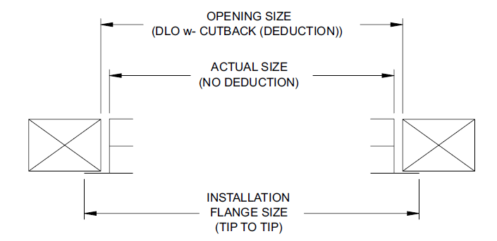
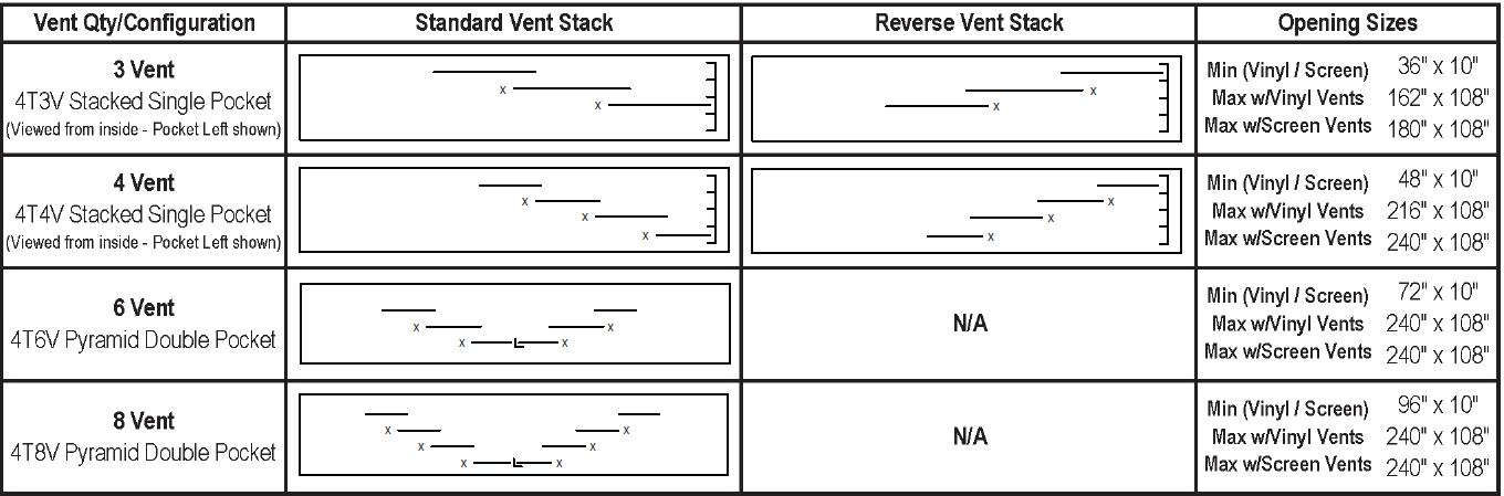
"Opening Size" measurements are preferred. All sizes must be given (width x height in inches) - see product specifications for standard cutbacks (deductions) or order by actual unit size.
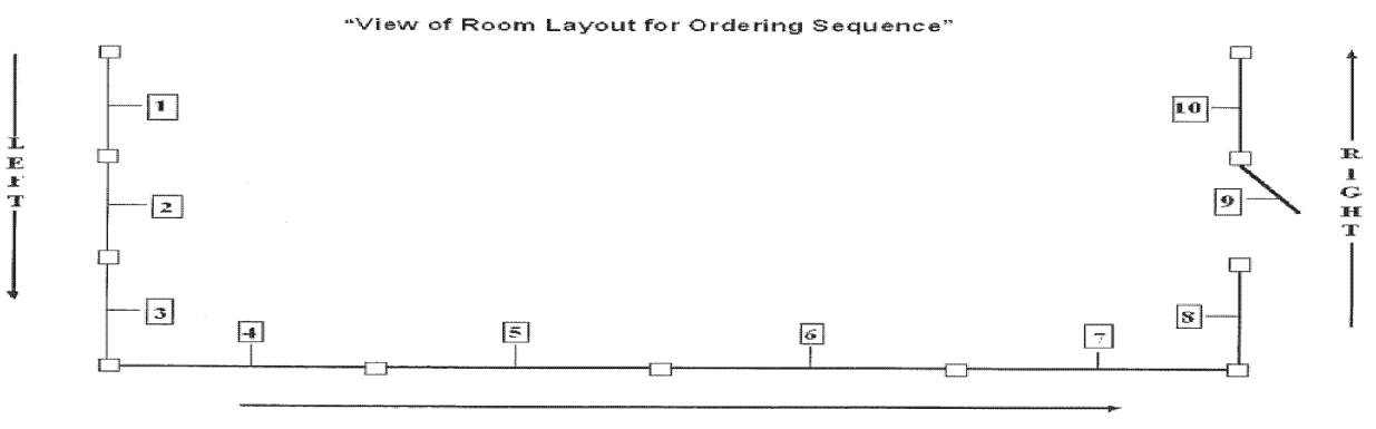
Upon request, PGT will number the units in the same order they are given thus avoiding confusion during installation. When measuring, start at one end and work your way around the room, numbering each opening in sequence and give your Customer Service Representative the unit sizes in the same order they were measured.
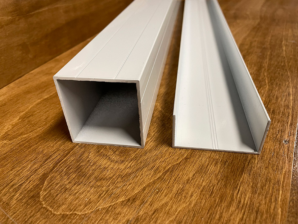
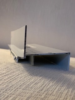
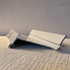
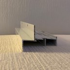
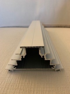
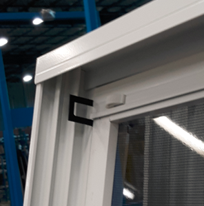
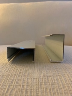
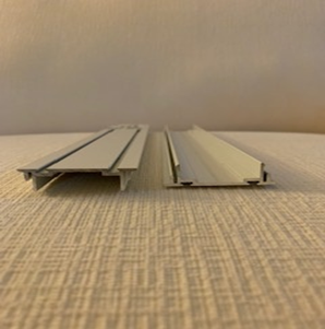
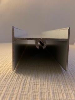
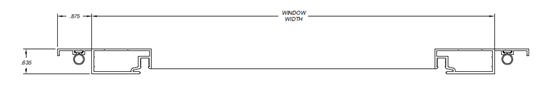
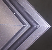
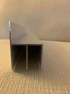
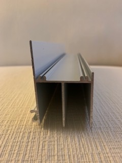
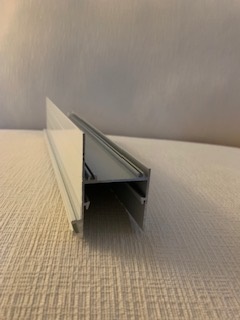
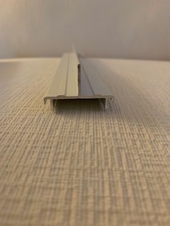
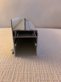
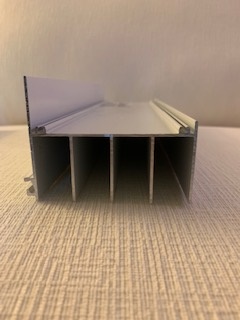
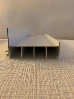
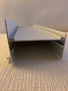
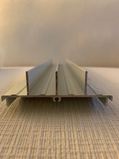
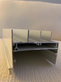
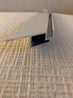
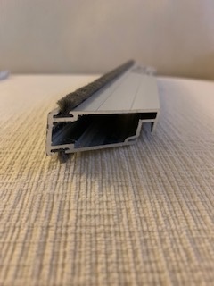
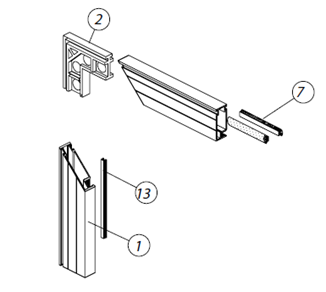
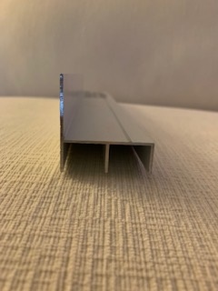
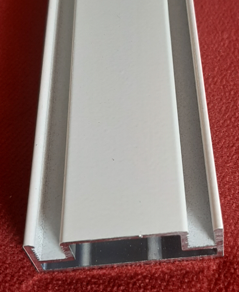
Mull Post C-Channel
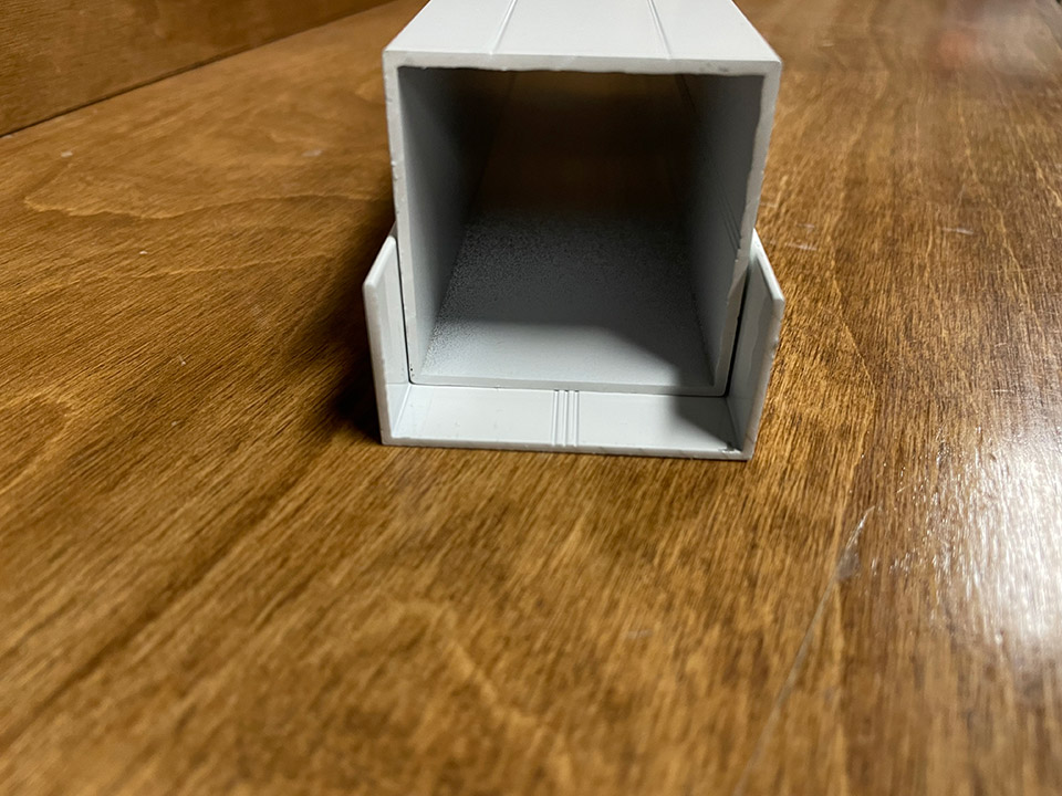
Mull Post fit into a C-Channel
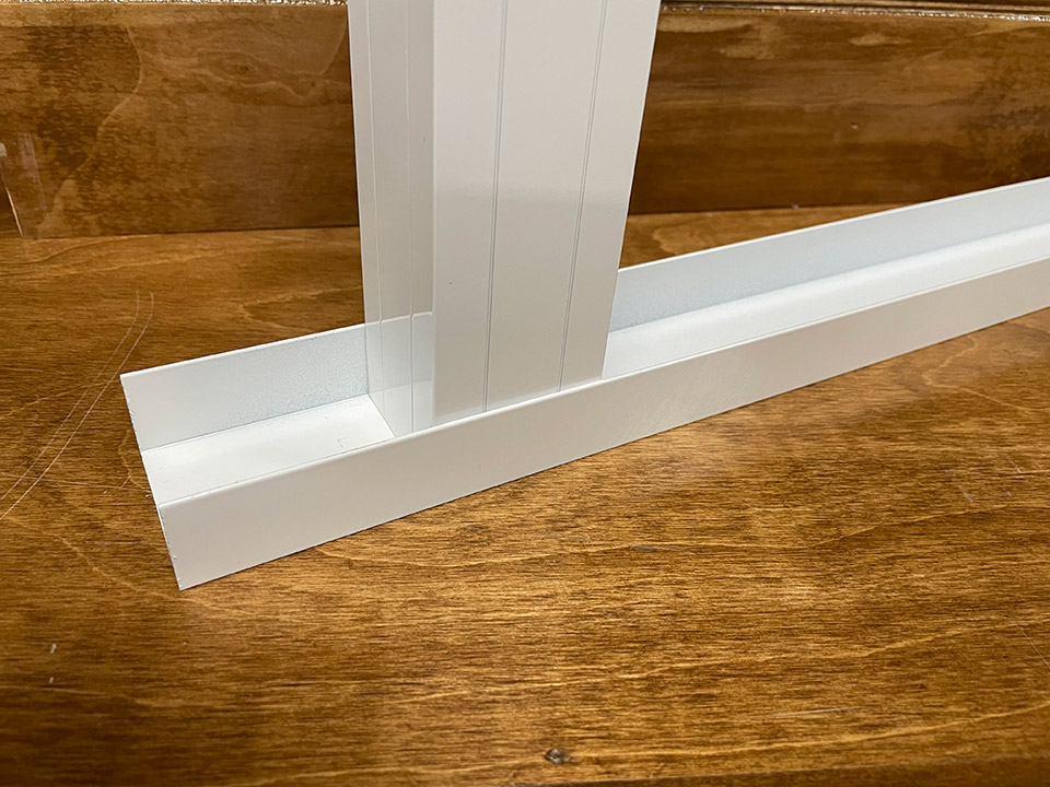
Mull Post fit into a C-Channel vertically
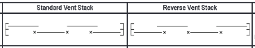
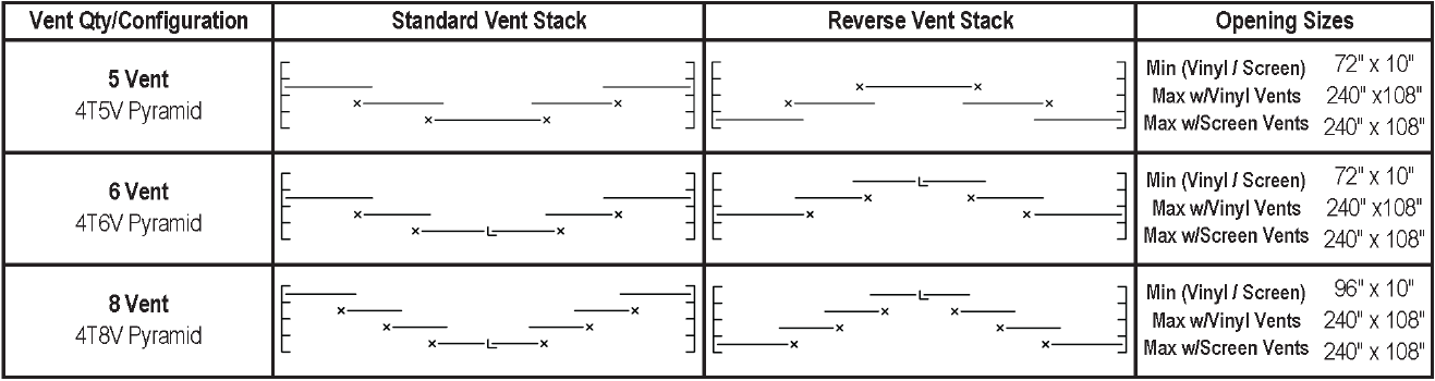
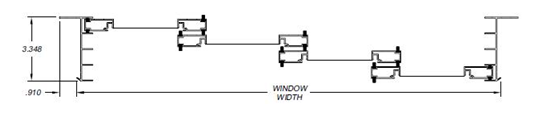
Spreader bars are required on actual unit widths that exceed 30” wide. It is recommended to use 2 spreader bars on units over 60” wide. If spreader bar is required based on size and “NONE” is selected, the warranty is void.
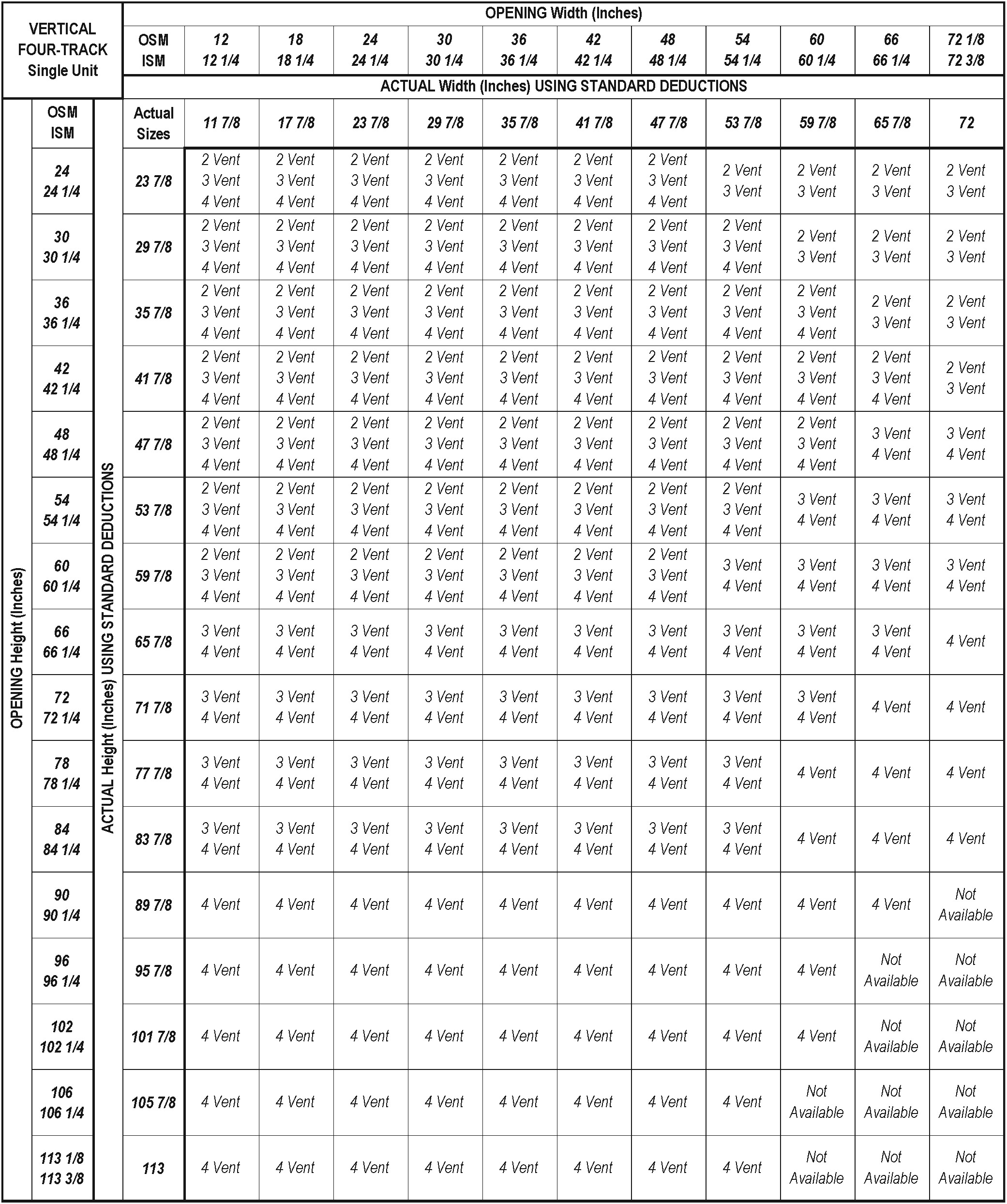
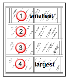
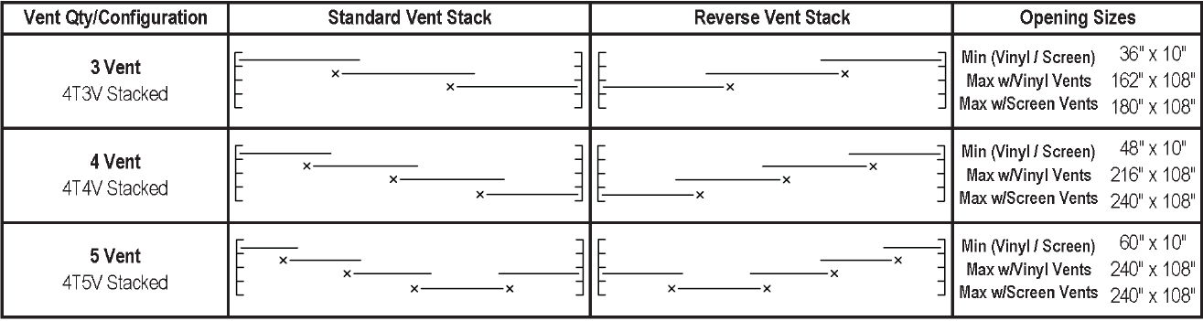
To use this chart with twin and triple units do the following:
Twin unit: divid opening width by 2 then locate that size on the chart above
Triple unit: divid opening width by 3 then locate that size on the chart above
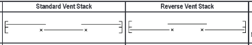
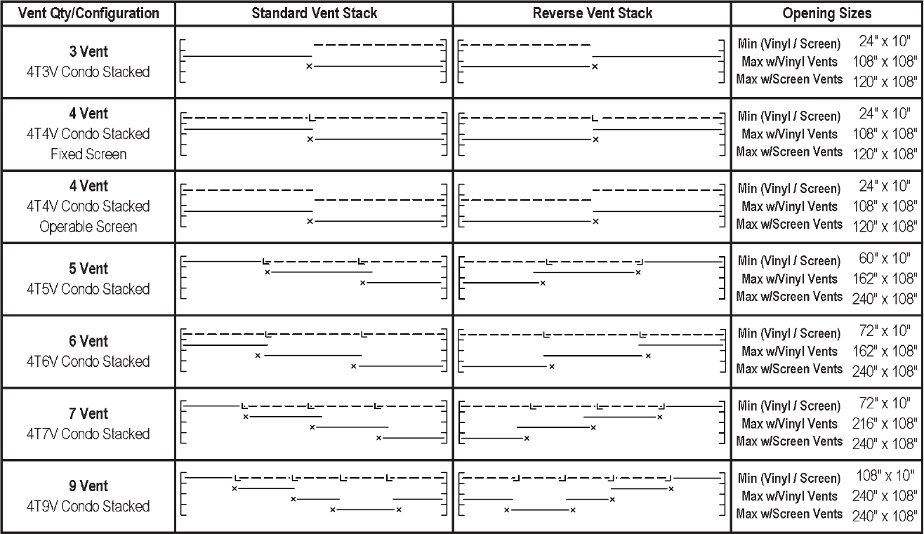
Spreader bars are required on actual unit widths that exceed 30” wide. It is recommended to use 2 spreader bars on units over 60” wide. If spreader bar is required based on size and “NONE” is selected, the warranty is void.
To use this chart with twin and triple units do the following:
Twin unit: divid opening width by 2 then locate that size on the chart above
Triple unit: divid opening width by 3 then locate that size on the chart above
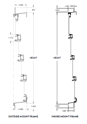
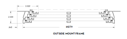
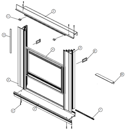
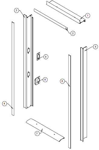
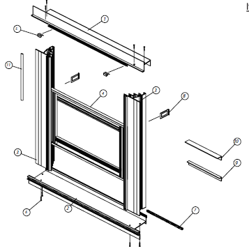
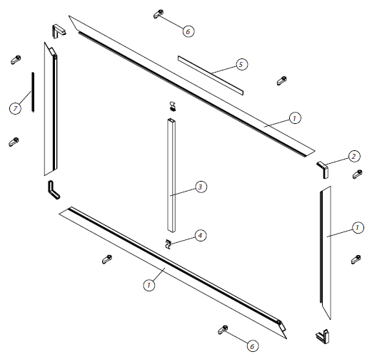
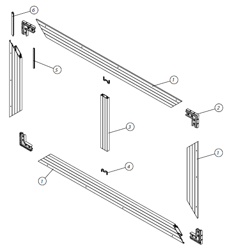
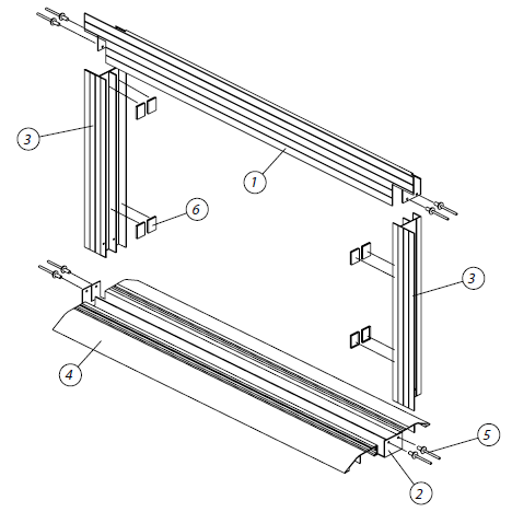
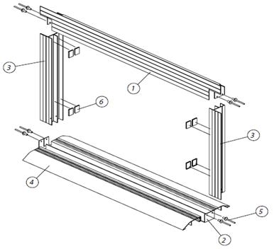
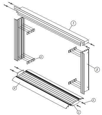
4V60 Outside Mount Frame Assembly
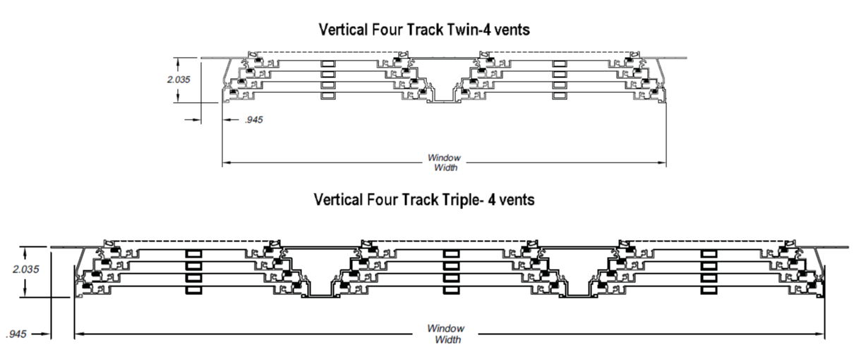
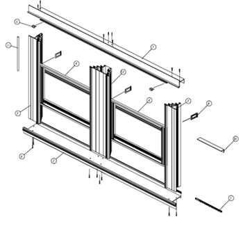
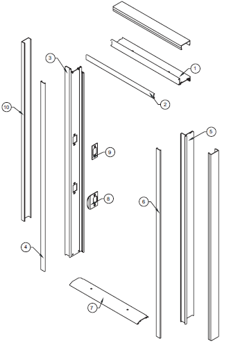
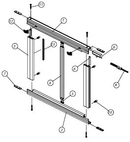
4V60 Outside Mount Frame - Twin Assembly
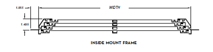
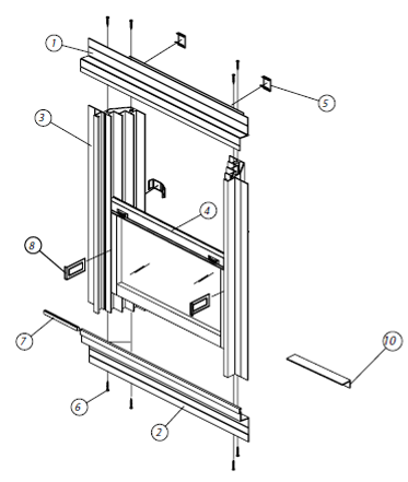
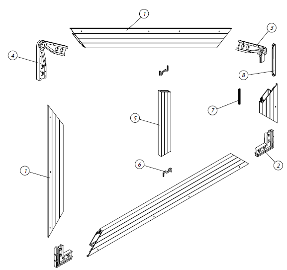
4V60 Inside Mount Frame Assembly
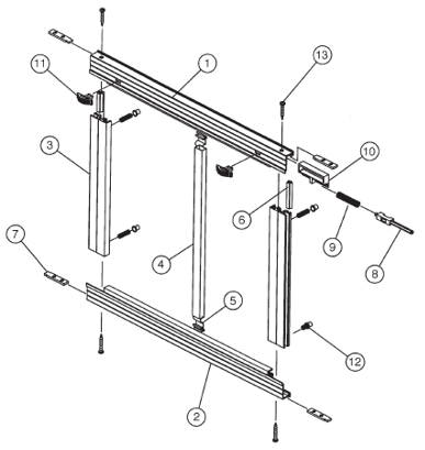
4V60 Vent Assembly (OSM/ISM)
4V60 Parts

Frame Jamb (OSM)
Frame Head (OSM)
Frame Sill (OSM)
Frame Jamb (ISM)
Frame Head (ISM)
Frame Sill (ISM)
Twin/Triple (intermediate) Frame Jamb

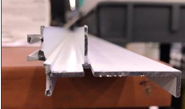
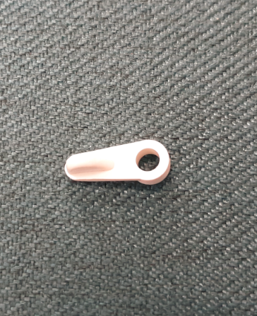
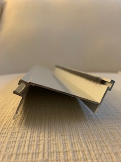
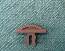
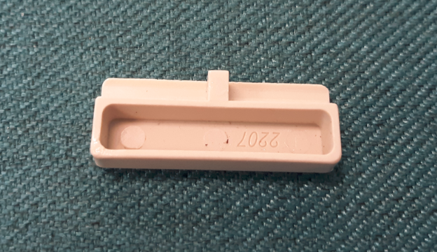
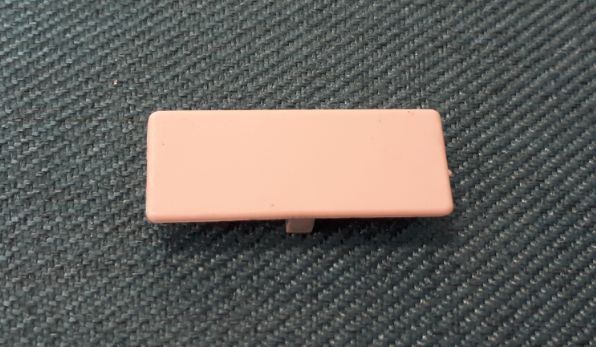
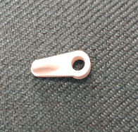
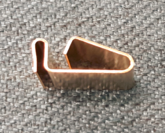
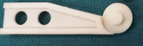
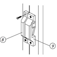
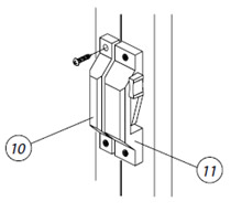
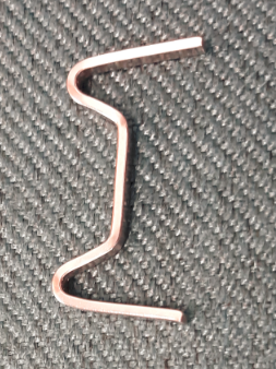
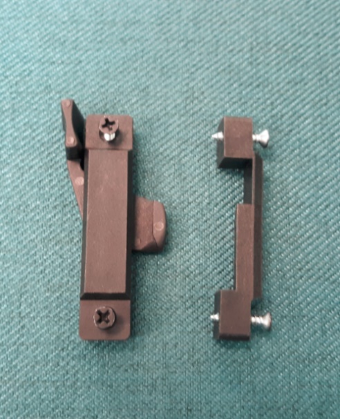
Top Vent Clip
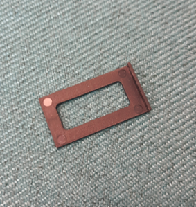
Installation Clip
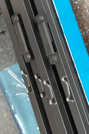
This clip is installed to the top vent. The dealer uses this as a guide for the install screws, top screw goes in this location, you then lower vent #1 down to interlock with vent #2, next screw goes there, you then lower vents #1 & #2 down to interlock with vent #3, etc.

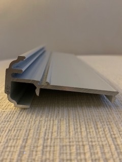
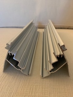
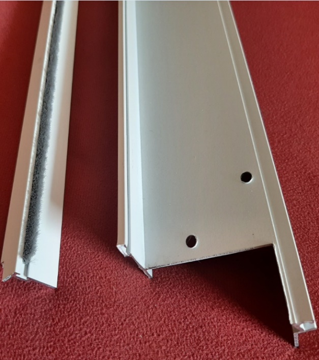
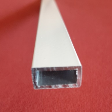
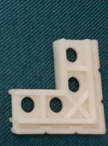
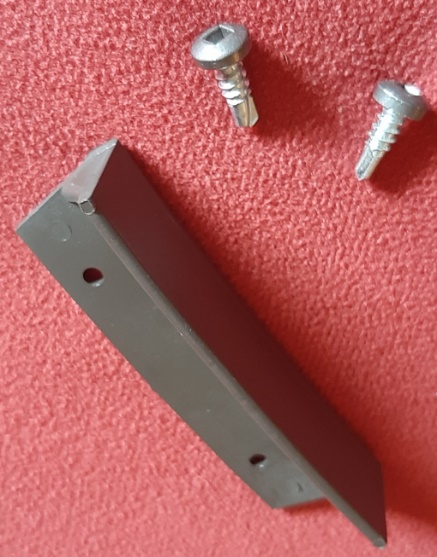
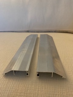
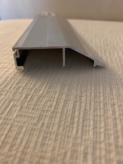
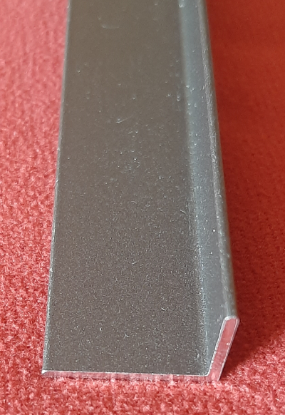
Track Filler Angle
This filler is installed into the main frame prior to assembly. It is used when the unit is only ordered with two or three vents to fill the sill, so dirt does not build up in the unused tracks.

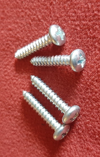
Frame Assembly Screw (#8 x .500)

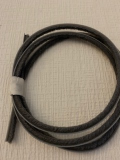
Flat Spline (used to roll screen into the main frame)
Jamb Fin Seal (vent)
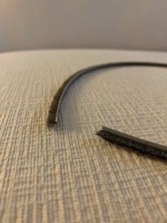
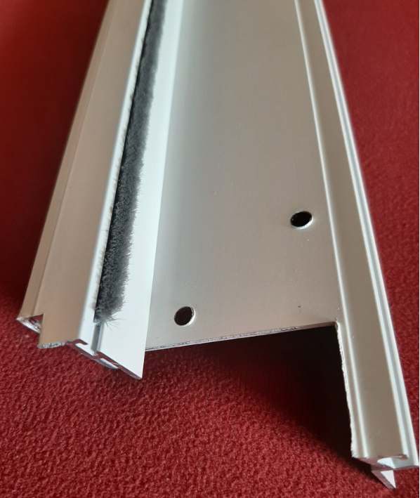
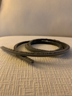
Sill Track Filler Weatherstripping
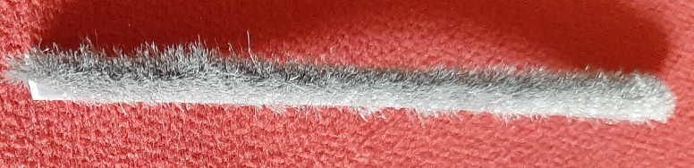
Fin Seal Weatherstripping (used on main frame sill)
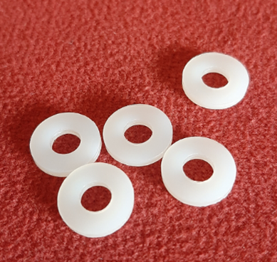
ISM Screen Spacer **
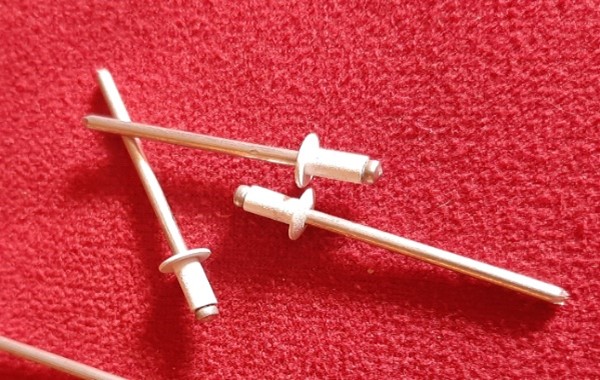
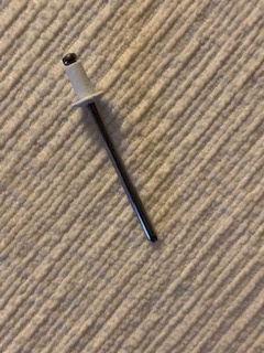
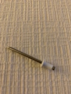
ISM Pop-Rivet (colour matched) **
** Used with screens attached only
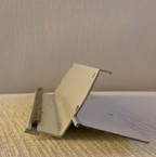
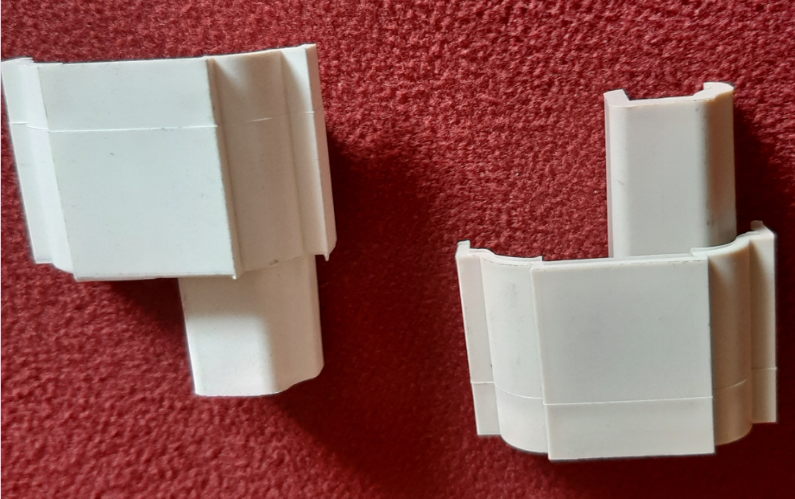
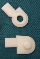
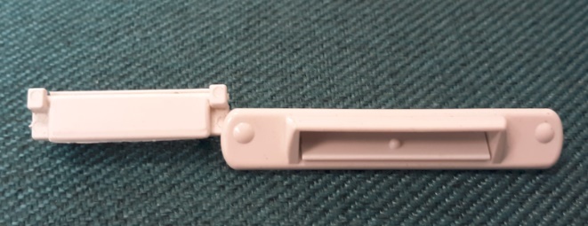
This is how the top of the vent is assembled

Slide Bolt Assembly (colour matched to vent extrusion)

Thumb Latch (colour matched to vent extrusion)
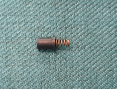
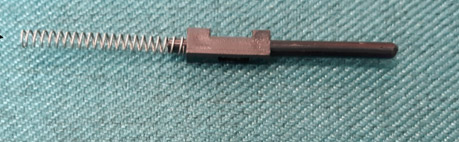
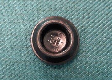
Spring Cap Assembly (colour matched to vent extrusion)

Vent Spacer (always black)

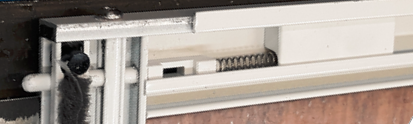
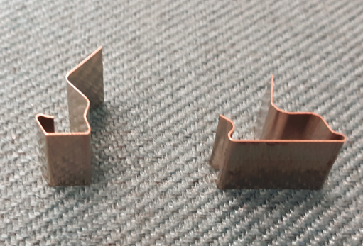
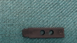
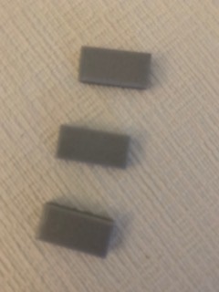
Spring Stop Block (front)

Spring Stop Block (back)

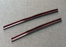
Spreader Bar Clip

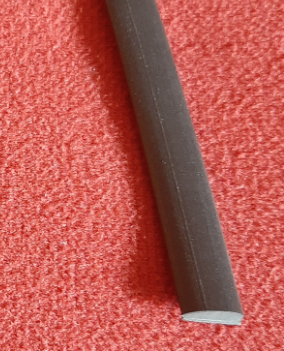
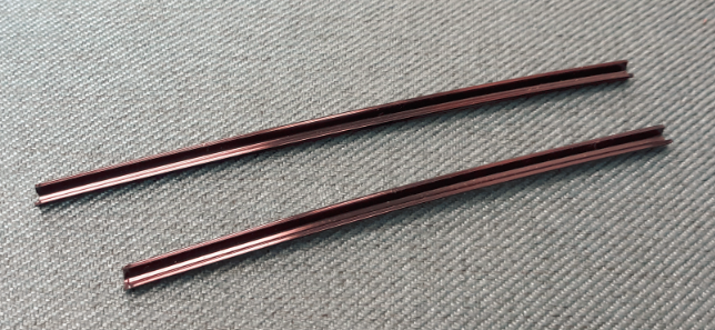
Spreader Bar
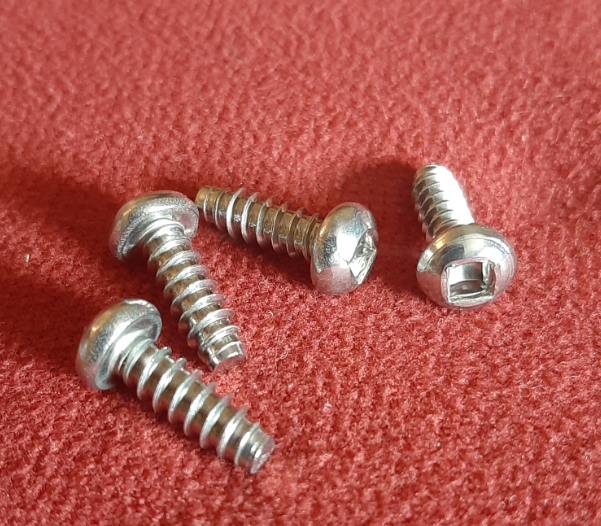
Vent Assembly Square Drive Screw (#8 x .500)

Rigid V-Spline (used to roll glazing material or screen into vents)

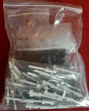
4V60 Goody Bag
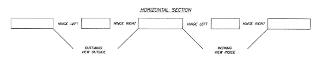
Double Door Hinge and Swing
All doors are viewed from the direction of swing.
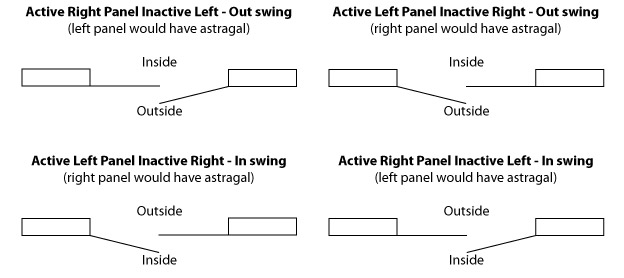
Inactive panels would swing open in the same direction of the active panel when the flush bolts on the astragal are unlocked.
Actual size measurement is preferred.
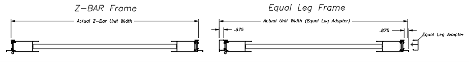
Box equal leg adapter can be added to Z-bar Frame.
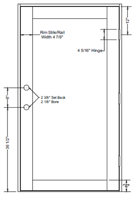
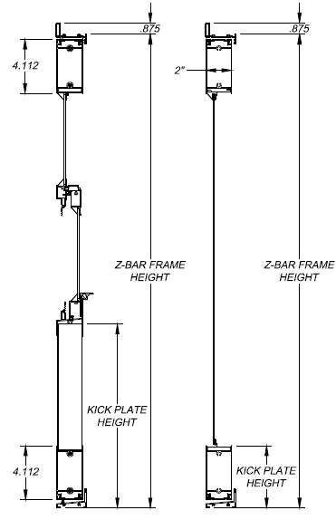
Kickplate dimensions are always measured from the bottom of the opening to the top of the kickplate.
Heights calculated here are for a slab with no adjustable bug sweep options.
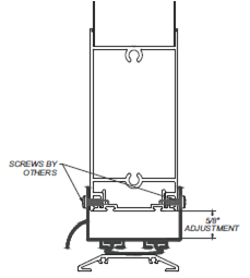
**Adjustable Bug Sweep is not available with a double CD90 configuration at this time**
Spreader bars are required when the window insert exceeds 30” wide. If spreader bar is required based on size and “NONE” is selected, the warranty is void.
Standard sizes are:
Custom sizes are available by quote only. Call 1 800 567 5872.
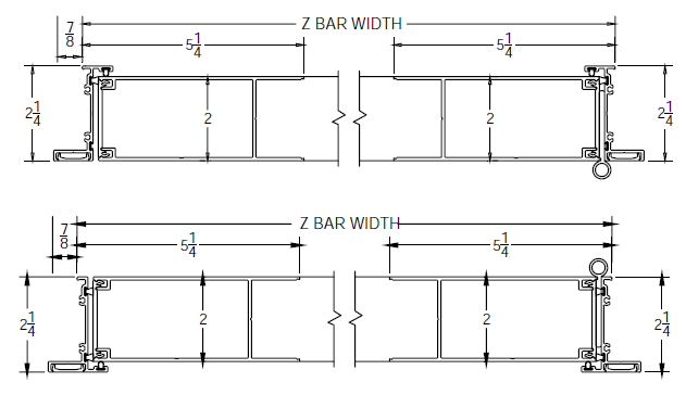
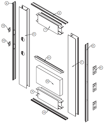
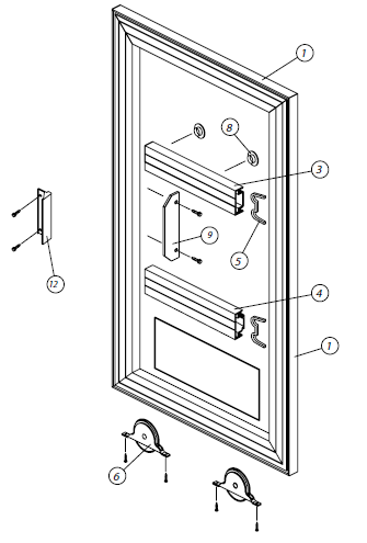
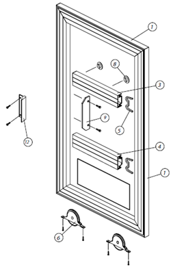
CD90 Z-Bar Frame Frame Assembly (single & double)
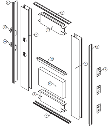
CD90 Box Frame Assembly (single & double)
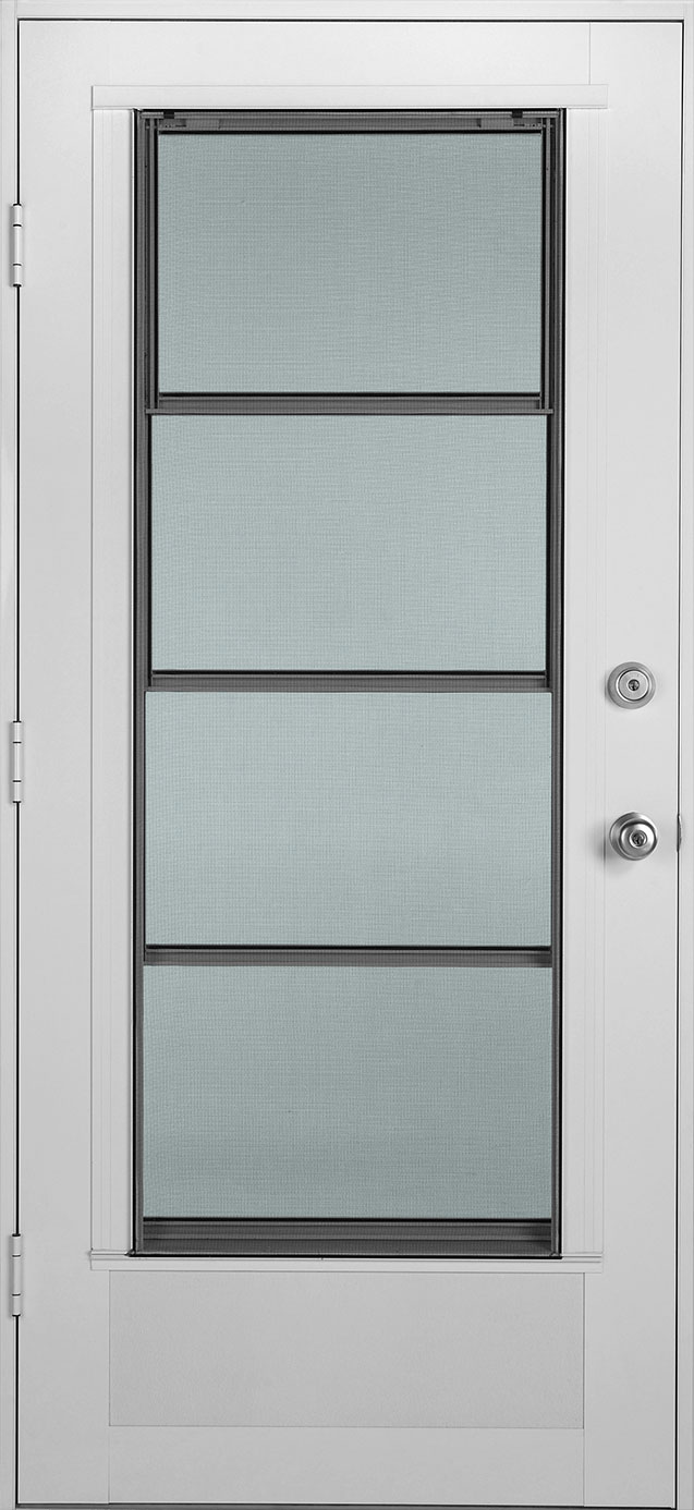
CD90 Cabana Door Slab Assembly (single)
CD90 Cabana Door Slab Assembly (double)
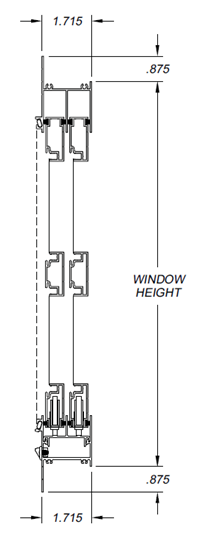
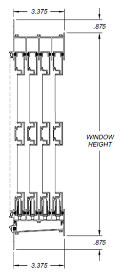
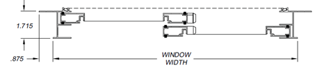
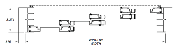
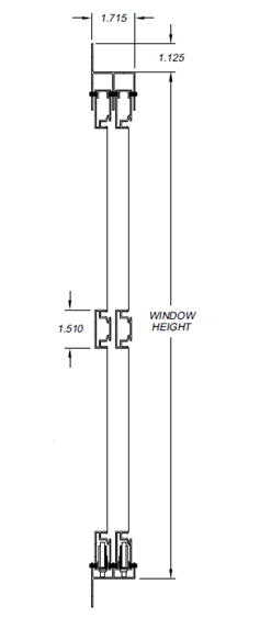
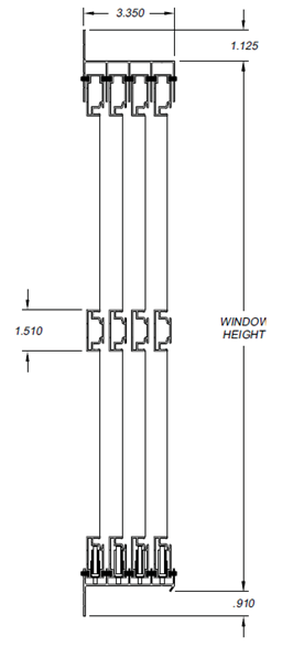
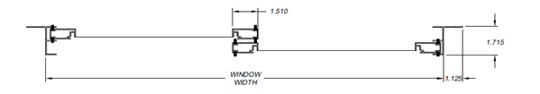
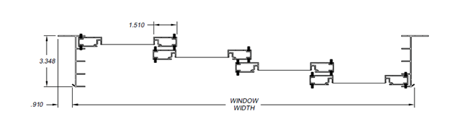
4V60 Vertical Four Track Window Style Assembly
4V60 Vertical Four Track Window Style Vent Assembly
CD90 Fixed Lite Window Style Frame Assembly
CD90 Parts
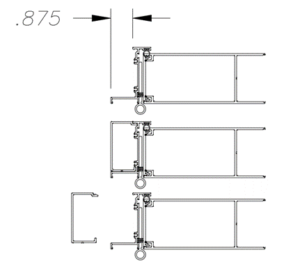
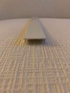
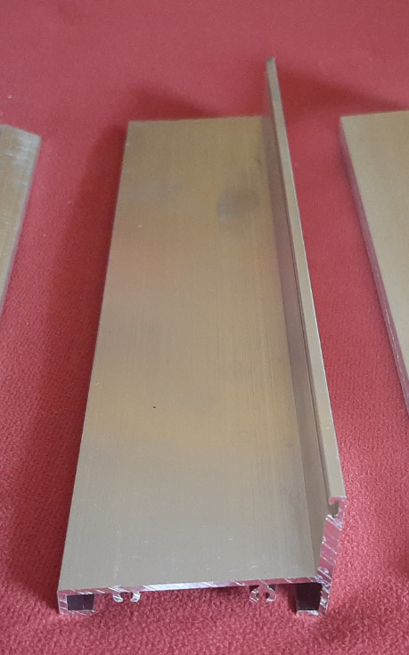
Head/Jamb Equal Leg Adapter
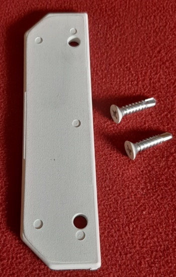
Frame Top/Bottom Backing Plate
Frame Screw Cover
Backing Strike Screw
Deadbolt Striker Backing Plate
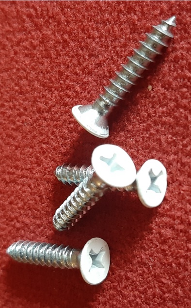
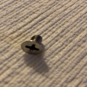
Frame Assy Screws (#6 x 3/4" Flat Phillips)
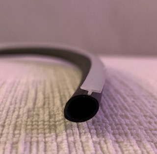
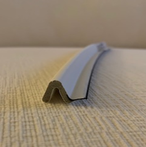
Frame Weatherstrip Bulb
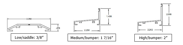
Low/Saddle
Medium Bumper
High Bumper
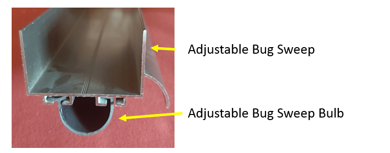
Adjustable Bug Sweep Bulb
Lock/Hinge Rail Backing Plate
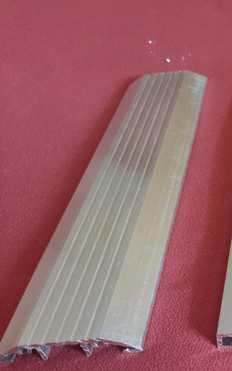
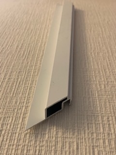
Astragal
Kickplate Cap
Astragal Weatherstripping
OSM LF20 Insert Frame Material
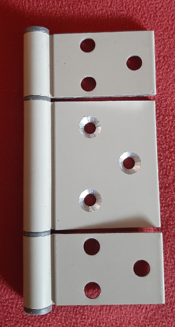
Hinge
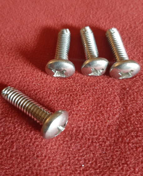
Slab Assy Screws (1/4" - 20 x 1")
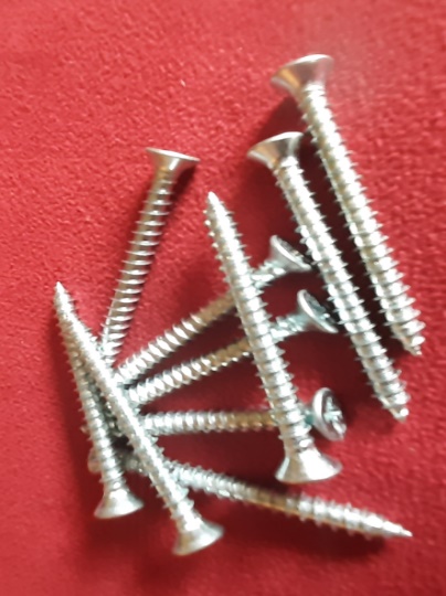
Installation Screws (come in a kit bag of 15 #10 x 2: Flat Phillips)
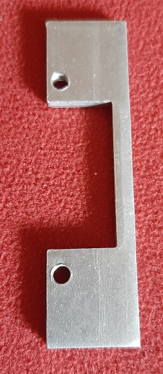
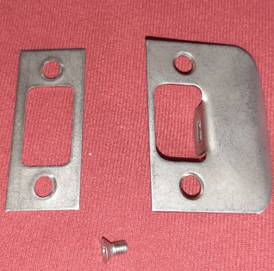
Knob Strike Backing Plate
Deadbolt and Lock Strike Plate
Astragal End Seal (for a double door)
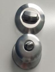
Knob and Thumb Turn
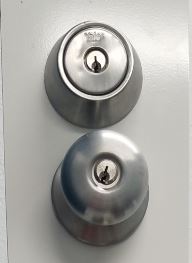
Knob and Deadbolt
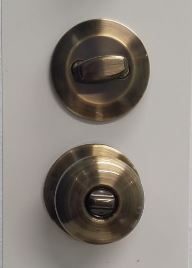
Knob and Thumb Turn
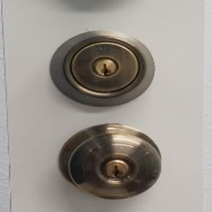
Knob and Deadbolt
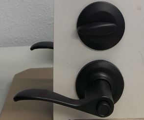
Lever and Thumb Turn
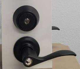
Lever and Deadbolt
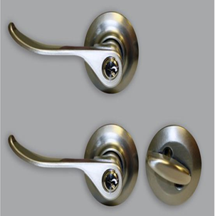
Lever and Thumb Turn
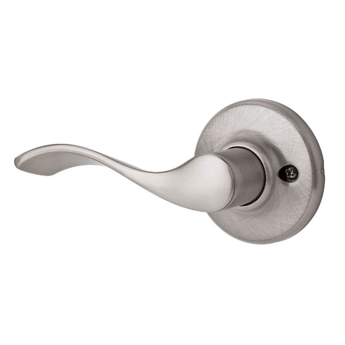
Passage Balboa Lever
Available in Satin Silver & Black Suede
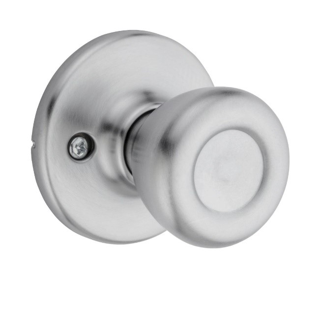
Passage Tylo Knob
Available in Satin Silver, Antique Brass, Polished Brass, & Polished Chrome
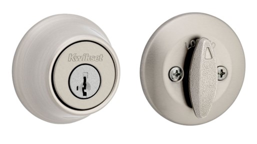
Deadbolt Lock Set
Features SmartKey Security™, which protects against advanced break-in techniques and allows you to re-key your lock yourself in seconds. SmartKey Security™ re-key technology is compatible with Kwikset (KW1) keyway or (SC1) keyway options. Deadbolt is operated by key outside, thumb turn inside. Comes with 2 keys.
LF20 Parts
LF20 Frame - Head/Sill/Jamb
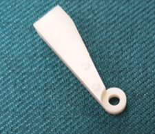
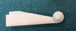
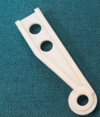
Swivel Clip
Rivet (colour matched)

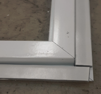
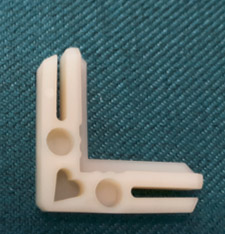
Female Adjustable Corner Key

Male Adjustable Corner Key

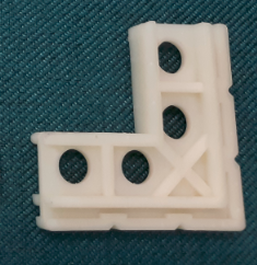
Standard Corner Key

Spreader Bar Clip

Spreader Bar
Rigid V-Spline
4V60 Parts
4V60 Frame Jamb (OSM)

4V60 Frame Head (OSM)
4V60 Frame Sill (OSM)
Top Vent Clip

Track Filler Angle
This filler is installed into the main frame prior to assembly. It is used when the unit is only ordered with two or three vents to fill the sill, so dirt does not build up in the unused tracks.
Frame Assembly Screws (this is the main frame assembly screw - #8 x .500)
Flat Spline (used to roll screen into the main frame)

4V60 Jamb Fin Seal (vent)

4V60 Sill Track Filler Weatherstripping

Fin Seal Weatherstripping (used on main frame sill)

This is how the top of the vent is assembled
Slide Bolt Assembly (colour matched to vent extrusion)
Thumb Latch (colour matched to vent extrusion)

Spring Cap Assembly (colour matched to vent extrusion)
Vent Spacer (always black)
Spring Stop Block (back view)
Spring Stop Block (front view
Spreader Bar Clip
Spreader Bar

Vent Assembly Square Drive Screw (vent assembly screw - #8 x .500)
Rigid V-Spline (used to roll glazing material or screen into vents)
4V60 Goody Bag

Spreader bars are required on actual unit size that exceeds 42” in width or height. If height is greater than width the unit will get a horizontal spreader. If Width is greater than height the unit will get a vertical spreader. Temporary spreaders are available for shipping and handling purposes. If spreader bar is required based on size and “NONE” is selected, the warranty is void.
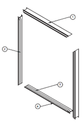
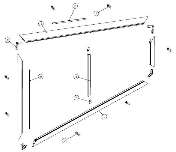
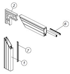
LF20 Standard Lip Frame Assembly (fixed lite)
LF20 Standard Lip Frame Assembly (trapezoid)
LF20/LS20 Parts
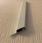
Frame - Head, Sill, Jamb
Foam Tape Applied
Swivel Clip

Rivet (colour matched)
Female Adjustable Corner Key
Male Adjustable Corner Key
Standard Corner Key

Spreader Bar Clip

Spreader Bar

Rigid V-Spline

Spreader bars are required on actual unit size that exceeds 60” x 48” or 48” x 60” in width or height. If height is greater than width the unit will get a horizontal spreader. If Width is greater than height the unit will get a vertical spreader. Temporary spreaders are available for shipping and handling purposes. If spreader bar is required based on size and “NONE” is selected, the warranty is void.
HLF20 Heavy Duty Lip Frame Assembly (fixed lite)
HLF20 Heavy Duty Lip Frame Assembly (trapezoid)
HLF20/HLS20 Parts
Heavy Duty Frame - Head, Sill, Jamb
Bulb Weatherstripping

Bulb Weatherstripping
Spreader Bar Clip
Spreader Bar

Rigid V-Spline
Female Adjustable Corner Key
Male Adjustabel Corner Key
Standard Corner Key
For use on really small legged shapes

Spreader bar(s) are required on actual unit heights that exceed 48” tall. If spreader bar is required based on size and “NONE” is selected, the warranty is void.


Maximum actual unit width: 192".

Spreader bar(s) are required on actual unit heights that exceed 48” tall. If spreader bar is required based on size and “NONE” is selected, the warranty is void.
Units that exceed 192" actual unit width, will be spliced. See guideline for details.
SS10 Outside Mount Frame Assembly
SS10 Outside Mount Vent Assembly
SS10 Inside Mount Frame Assembly
SS10 Inside Mount Vent Assembly
Available Colours: White, Beige, Pebble Khaki, Bronze, Black
ISM Head 2T

ISM Jamb/Sill 2T

ISM 4T Head
OSM 2T Head
OSM 2T Sill
OSM 2T Sill Cover
OSM 2T Sill/Sill Cover Combined
OSM 4T Head
OSM 4T Jamb
OSM 4T Sill
OSM 4T Sill Cover
OSM 4T Sill/Sill Cover Combined
Lip Frame Head/Sill/Jamb
Top/Bottom/Side Rail (vent/head/jambs/sill)
OSM Lip Frame Spreader Bar

Spreader Bar Clip

Latch Assembly
Lock installed above spreader bar clip

Spreader Bar

Angle (installed where vents meet on same track)
Frame Assy Screws (used on OSM) #6x3/4"

ISM/OSM Weep Hole Covers
Lip Frame Vent Corner Key

Stainless Steel Neoprene Roller and Wheel Screw
Pull Handle with 1/2" Tek Screw

Frame Bumper
Weatherstrip - Jamb/Vent
Rigid V-Spline

Rivet - used on ISM Frame Assembly w/Screens
2T/4T Gasket Sill - OSM
Spreader bar(s) are required on actual unit heights that exceed 48” tall. If spreader bar is required based on size and “NONE” is selected, the warranty is void.
Maximum actual unit width: 192".
SS30 2-Track Frame Assembly
SS30 4-Track Frame Assembly
SS30 Vent Assembly
Available Colours: White, Beige, Pebble Khaki, Bronze, Black
ISM - 2T Head/Jamb No Flange
ISM - 4T Floor Sill No Flange

ISM - 2T Head
ISM - 2T Jamb/Sill
ISM - 4T Head
ISM - 4T Sill w/Flange
Top/Bottom/Side Rail (vent/head/jamb/sill)
Spreader Bar w/Kickplate Groove
Threshold both Sides
Threshold 1-Side of Sill
Spreader Bar Clip
Latch Assembly

Lock installed above spreader bar clip
Spreader Bar
Vent Angle (installed where vents meet on same track)

Frame Assy Screws #6 x 3/4"
Weephole Covers
Thumb Pull

Vent Corner Key
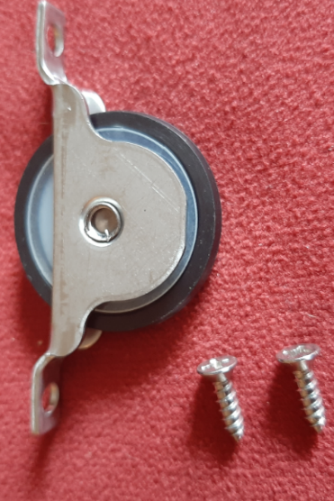
Stainless Steel Neoprene Roller w/Screws

Pull Handle with 1/2" Tek Screw
Panel Come Along with 3/4" Tek Screw
Frame Bumper

Weatherstrip - Jamb/Vent

Rigid V-Spline
Rivet